Adder bit logisim using circuit full alu complement cs create unsigned lab1 cornell courses labs edu lab re save ta Electrical – designing a 4-bit adder-subtractor circuit – valuable tech 4 bit binary adder circuit diagram
4 Bit Adder Schematic
Adder logic
4 bit adder schematic
4-bit binary adder-subtractorSchematic of 16-bit brent-kung adder using transmission gates 4 bit adder schematicCircuitverse 4 bit binary adder subtractor with overflow detection.
Adder cmos proposed technique soi4 bit binary incrementer 4 bit adder schematic wiring total4 bit adder subtractor circuit diagram.
![4 Bit Binary Incrementer - GeeksforGeeks](https://i2.wp.com/media.geeksforgeeks.org/wp-content/uploads/20210429115859/modifieddetailed.jpeg)
4 bit adder schematic
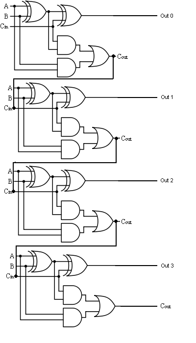
[diagram] logic diagram of 4 bit ripple carry adderFull adder logic gate circuit diagram template logic logic gates 4-bit adder subtractor1 bit full adder logic diagram.
[diagram] logic diagram of 4 bit full adder4 bit binary adder circuit diagram Adder bit schematic gates kung brent adders efficientDownload 4 bit adder circuit stick and logic diagram.
![⚡ 4 bit parallel adder theory. 74LS83 4. 2022-10-05](https://i2.wp.com/media.geeksforgeeks.org/wp-content/cdn-uploads/full_adder.png)
8 bit parallel adder circuit diagram
Adder bit full spice youspice electronics digital projects4-bit adder and subtractor circuit explained 4 bit adder diagramBit binary bits output geeksforgeeks incremented.
Circuit diagram of a one-bit full adder using the proposed technique inEfficient 8-bit adder subtractor circuit: simplified diagram The answer is 42!!: four bit full adder tutorial4 bit adder circuit.
![8 Bit Parallel Adder Circuit Diagram](https://i.pinimg.com/originals/f2/10/6b/f2106ba94a053f31142f3b484e027d00.png)
8-bit adder circuit diagram
3 bit full adder⚡ 4 bit parallel adder theory. 74ls83 4. 2022-10-05 2 bit binary adder circuit diagram4 bit adder circuit diagram.
.
![4 Bit Adder Schematic - funkyqlero](https://i2.wp.com/funkyqlero.weebly.com/uploads/1/3/4/1/134123071/578204312_orig.gif)
![The Answer is 42!!: Four Bit Full Adder Tutorial](https://4.bp.blogspot.com/-B8G0BfT9CeM/VI3992oIjNI/AAAAAAAAJzc/t4uaEaN2H7o/s1600/4-bit-full-adder%2Bcircuit.jpeg)
![8-bit Adder Circuit Diagram](https://4.bp.blogspot.com/-NIy45k3TuEE/TkouUTvUOZI/AAAAAAAAAG8/SQiB48Yi_UQ/s1600/550px-Full-adder.png)
![Schematic of 16-bit Brent-Kung adder using transmission gates](https://i2.wp.com/www.researchgate.net/publication/258403733/figure/fig4/AS:670698922070026@1536918492150/Schematic-of-16-bit-Sklansky-adder-using-transmission-gates_Q640.jpg)
![4 Bit Binary Adder Circuit Diagram - Wiring Diagram](https://i2.wp.com/eevibes.com/wp-content/uploads/2022/06/4-bit-adder-subtractor-circuit.png)
![Combinational and sequential design of a 4-bit Adder. (a) HA circuit](https://i2.wp.com/www.researchgate.net/publication/283633559/figure/fig2/AS:363942875549699@1463782151965/Combinational-and-sequential-design-of-a-4-bit-Adder-a-HA-circuit-b-FA-circuit-c.png)
![2 Bit Binary Adder Circuit Diagram](https://1.bp.blogspot.com/-ovoQJDsPU0I/U-mnSZ2WG3I/AAAAAAAAAPY/vsK2exWgEKY/s1600/1111.jpg)
![4 Bit Adder Schematic](https://i2.wp.com/image.slideserve.com/798121/full-adder-schematic-l.jpg)
![4 Bit Adder Circuit Diagram - Caret X Digital](https://i2.wp.com/www.electronics-tutorial.net/wp-content/uploads/2015/05/Add_Sub.png)